Category Archives: Software and Rig Control

KST Download and Setup

wtKST is a clean, simple user interface to the ON4KST online chats – with some extra features for Aircraft Scatter prediction.

Download the latest version: https://github.com/dl8aau/wtkst/releases

wtKST was written by DL2ALF, the author of the AS prediction program AirScout and the two programs are linked. If AirScout is running in the background, wtKST will check the list of stations that are logged into KST and alert you about possible AS opportunities. Click on a callsign and the AirScout map will appear with more information.

Note: wtKST is now being maintained by Alex DL8AAU. Please do not ask questions to DL2ALF!

wtkst

wtKST has one fixed-format screen, divided into four main areas:

  1. All the chat traffic (Left) – just like the official ON4KST chat interface (and just as unreadable when the bands are busy)
  2. A ‘filtered’ chat window (Lower Left) containing only the messages to and from yourself (like the KST2me filtered chat, but no setup required)
  3. Message input line (Top Left).
  4. KST login list (Right). If AirScout is also running, this is where the added info about AS opportunities will appear (see below).

wtKST is less configurable than either the ON4KST interface or KST2me by OZ2M – but the features you most want are already there. They are also easy to use:

  • To send a message: left-click on any callsign on the login list. /cq [callsign] appears in the message entry line (top Left). Add the rest of your message and click Send.
  • See your personal message traffic in the lower window (including your own outgoing messages if that option is selected – see below).
  • Resize the chat windows – you can click-and-drag the boundary between All Messages and My Messages at any time you need.

wtKST Setup

You should only need to do this once. – just follow these instructions.

  1. Before you begin: you must already have signed up with the official ON4KST site to register your username and password. (Remember to exit from the ON4KST program!)
  2. Download the latest version from https://github.com/dl8aau/wtkst/releases
    Unzip the .zip file to a directory of your choice, and wtKST.exe should run.
  3. In wtKST: click Options, choose the KST tab, and enter that same login information. Also enter your station info and other selections.

kst tab

  1. Next, click the Calls tab and choose which bands and stations you want to display.

calls tab

  1. Move along to the Airplane Scatter tab and check the two boxes below (use the default server settings). The bottom line lets you choose the minimum and maximum aircraft ranges you wish to know about.

scatter tab

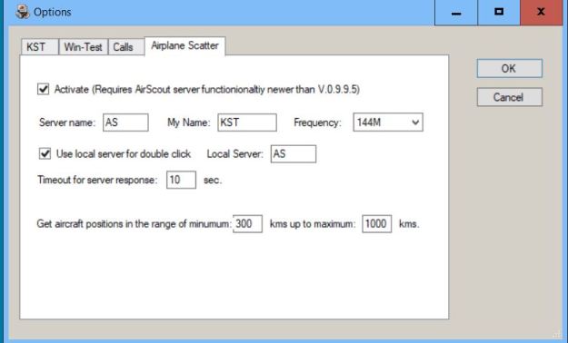
    1. Close the Options dialog and you re ready to go –  wtKST is now your window into the selected ON4KST chat.
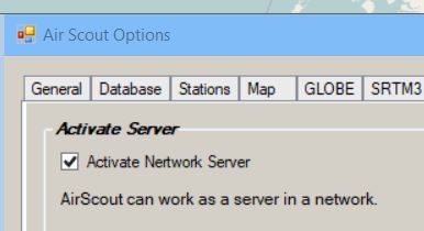
    2. To get the information from AirScout, open that program, and choose Options from the main screen. Select the Network tab and check Activate Network Server.

as activate tab

wtKST will now begin to highlight Aircraft Scatter opportunities with various stations in the Right-hand columns. (The quickest way to populate these columns is to open AirScout before you start wtKST.)

wtKST In Action

The chat function has already been described. The rest of this section is about the extra features in the Right-hand columns of the wtKST display.

NB: you will only see info about stations that are logged into KST. Don’t forget there are other stations on the band too!

      • The Call column is obvious. Left-click on the word Call to sort the list into callsign order. (Left-click again on the Call header to remove this feature.)
      • The A or Activity column shows the number of minutes since that station posted to KST. Left-click on this column header to prioritize the most active posters (Left-click again on the A / Act header to remove this feature.)
      • To see information about a station – including distance and beam direction – move the pointer over that station’s Call, Name, Locator or Act.
      • To send a message to someone, Left-click on that station’s Call, Name, Locator or Act. Then type into the message input line (see above).
      • The AS column shows Aircraft Scatter opportunities for each station. This powerful feature is unique to wtKST, but it is only active if AirScout is already running.
        – Same as with AirScout, purple blobs in the RH columns mean “AS to this station is possible now!”  Red followed by a number means “AS coming soon, in n minutes”. Brown/orange means “aircraft is on track, but currently too low”. Bigger blobs indicate more/better opportunities.
        – Depending on your minimum and maximum distance settings (see wtKST setup above),  you may also see < which means “Too close for AS”, or > which means “Too far away for AS”.
        – Left-click on these indications to open the main AirScout map, showing the AS path to the selected station.
        – Right-click in this column to see details of the target aircraft.
      • The far Right-hand columns indicate which bands a station is active on (probably according to their information in the AirScout database). You can click on these colours to change them in your own display.

If you have further info about the wtKST setup and user interface, please post a comment here so I can update the blog. Thanks for all suggestions! 

“Play Nicely Together”: Integrating the K3, SDRplay RSP1, HDSDR and N1MMlogger+

HDSDR and N1MM+

These notes describe how to configure the HDSDR software to allow your SDR to act as a 2nd receiver, fully co-ordinated with your existing transceiver and logging software.

The procedure has been tested with the Elecraft K3 but should also work with any OmniRig compatible transceiver.

1. Create a Virtual Port Splitter

The COM port numbers used below are typical examples only, and could be changed. However, it is good practice to keep virtual port numbers well separated from physical port numbers, so I begin my virtual port numbering at COM11.

[ Physical and Virtual COM ports:
COM ports are used for serial data communication. Physical COM ports are associated with real hardware connectors. In older PCs these were 9-pin ports for RS232 communication, but in modern PCs these are typically USB sockets.
Physical port numbers are allocated by the operating system and are usually single-digit numbers starting from COM1.
Virtual ports exist only in software, and their numbering is normally user-configurable.]

The transceiver is connected to the PC using the USB port (in my example, COM6). But a physical COM port can only support one program at a time – any other programs trying to connect to that port will produce error messages about port conflicts.

We get around this problem by using Virtual Serial Port Emulator from www.eterlogic.com/Products.VSPE.html  The 32-bit version is freeware, but the 64-bit version requires a contribution to help pay for software licences.

vspe1

VSPE has a “virtual port splitter” facility which can connect to a physical COM port (COM6 in this example) and then creates multiple instances of a virtual COM port with a different number (which I configured as COM11). These virtual COM11 ports are all identical, but are hidden from each other by the VSPE program. This allows several different programs to connect to the same virtual “COM11” port.

VSPE’s description of a virtual Splitter ‘device’.

VSPE must be started first, to create those virtual COM11 ports. When you start up each program, its own port configuration menu will now include COM11 so that is the one you should select (COM6 will still be listed, but make sure you don’t connect to that any more).

These menu selections show how to configure the port splitter:

vspe2

2. Start your logging software

Now you can start up your existing logging program, reconfigure it for the new virtual port COM11 and make sure that it talks to your transceiver exactly as it did with the old hardware COM port connection. The logging program should be able to control the transceiver, and the logging software should also follow any frequency/mode changes that you make on the transceiver.

3. Connect your SDR

Now is also the time to connect your SDR and arrange for its RX feed.  Usually this will come from the transceiver, either a dedicated IF output or a signal-frequency feed which is shared with the transceiver itself (typically a rear panel RX OUT connector).

For HF you can probably connect the SDR to the HF transceiver’s own dedicated IF output (at 8.215MHz in the case of the K3). However, if the transceiver is connected to a VHF/UHF transverter, a better signal/noise ratio will probably be available at the output of the transverter (typically 28MHz). Use a 3dB hybrid splitter to isolate the HF transceiver from the input to the SDR, reducing the possibility of birdies.

CAUTION: make sure that your SDR cannot be overloaded and damaged by your transmitter!

Next you can start up HDSDR. When you configure HDSDR for COM11 (details below) there should be no error messages about port conflicts. When everything is working OK, go back into VSPE and save your port-splitter configuration as a .vspe file that can be loaded automatically at startup.

4. HDSDR configuration

HDSDR2

HDSDR control panel. Lower right is a magnified spectrum/waterfall display of the current frequency (144.388MHz). Ctrl+Shift toggles the whole control panel on/off. For menu options, click Options or press F7.

Assuming that you already have HDSDR set up and working with your SDR as a standalone program, most of the additional changes can be found in the following HDSDR sub-menus (F7 or click Options on the control panel).

4.1 Options > CAT to Radio (OmniRig) > OmniRig Settings

Configure Port to the number of your shared virtual port (eg COM11). The rest of your port settings should be pretty much the same as you were already using. However, you should set RTS and DTR to be permanently Low so that HDSDR cannot accidentally key the transmitter.

4.2 Other settings in Options > CAT to Radio (OmniRig)

  • Sync Rig 1 = ON
  • Sync To OmniRig = ON
  • Sync From OmniRig = ON

Those three settings should ensure that your transceiver, logging program and HDSDR can all communicate with each other. However, I noticed that the VFO B knob on the K3 has considerable delays in tuning the SDR, so I normally tune HDSDR directly with the mouse. Click on the waterfall for large frequency changes and then roll the mouse wheel for fine tuning.

Also set Sync Tune Frequency = ON. (Do not select Sync LO because the LO frequency needs to remain fixed.)

4.3 Options > CAT to HDSDR

Not needed. Just make sure that Activated = OFF (unchecked).

4.4 Options > RF Front-end Config

Full sync in both directions = ON

With my VHF and UHF transverters, I use Transverter mode to give a direct signal-frequency display. For direct HF operation you will need one of the other options (which I haven’t explored).

4.5 LO settings

I always tune the band with a fixed frequency span, covering the whole range of interest and remaining static on the screen. This is important to maintain the straight vertical waterfall display (see the header photo above).

Setting the frequency span is not easy in HDSDR. You have to juggle the Spectrum Zoom slider on the control panel to set the desired width of coverage (very delicate) and each time you do that, the spectrum frequency scale ribbon will move as well. Drag the spectrum scale ribbon sideways to make it cover the exact frequency span required. This may require a few iterations between the two controls – and then be very careful not to move it again!

With the 2m transverter I select 144.150-144.400 which is the normal contest sub-band. The LO frequency then needs to be approximately centered within the display span, which in this example is 144.275.

You should now be able to QSY by clicking on either the HDSDR waterfall or the cursor in the spectrum segment. Watch to see that the transceiver follows these changes.

4.6 Choose the correct VFO

A small problem: at the moment you’re tuning the wrong VFO in the K3! The default in HDSDR is VFO A, but if you want to use the SDR as a second receiver you’ll normally need to link it to the K3’s VFO B. Fortunately it’s easy to change. On the HDSDR  frequency control panel, click on [A] (the small square box to the right of LO) and that label will change to [B]. You should now be able to tune VFO B correctly instead.

Notice that the LO frequency should not be changing (it will only change if you move completely outside of the visible frequency span.) If the LO frequency has changed for some reason, reset it to the centre of your desired display span.

Finally, right-click on the word LO to lock the LO.

At switch-on, HDSDR will restart with your previous LO and Tune frequencies, but it always defaults back to VFO A with the frequencies unlocked. You simply need to repeat the little routine above.

CAUTION:  When in use, VFO control of the K3 can occasionally jump back to VFO A.  This seems to happen if the VFO A and B frequencies are too close (eg if you have pressed A=B on the transceiver). VFO tracking can usually be reset to follow VFO B by splitting the two frequencies more widely apart, and then repeating the routine above.

4.7 HDSDR screen

I prefer the configuration in the header photo above, with a very small spectrum on top and the largest possible waterfall below. This maximizes the time history that is visible on-screen.

Setting the desired frequency span is described in 4.5 above.

The HDSDR control menu and the small passband spectrum appear in the lower part of the HDSDR window, but once your setup is OK you can press Shift-C to close those displays, and then the waterfall can flow further downward.

CAUTION: Your logging software probably has a very large number of keyboard shortcuts… but so too does HDSDR, and many of them use the same shortcut keys. Take great care that the Windows focus is on the correct program before you start typing!


Those settings should get you there… or at least somewhat closer to SO2V using HDSDR as the second receiver.

If this works for you, there are also ways to automate the setup and shutdown.

Special thanks for all the help and support from David, GM4JJJ.


Ian White GM3SEK
v2, 2017-09-30