Category Archives: Antennas, Baluns and EMC

The Private Life of Coaxial Cable

This is a common theme from several of my talks over the years about Ferrite Chokes and Baluns. By expanding the topic into a blog format, I hope to be able to explain it in more detail, and add some FAQs as time goes on.

This well-known image originated with Walt Maxwell W2DU, the author of many articles about transmission lines. It brings out several important points.

  • The inside of a coaxial cable truly is “private” – completely screened from the outside world. This is one of the rare statements that can be handed to absolute beginners as a simple fact, and still remains valid all the way through to graduate-level EM physics.
  • The private interior of coax is due to the skin effect which means that, at RF, current flows only on the surfaces of conductors.

    There are many confusing illustrations in textbooks that make some people imagine the skin effect only applies to electrical conductors of some particular shape and size, or in some particular type of circuit. That isn’t true! The best and most generalized derivation of the skin effect I have been able to find is reproduced here. All the high-level EM physics and maths leads to a simple and very powerful conclusion:
    Whenever and wherever an RF current is flowing (regardless of the circuit configuration, regardless of the reason) the skin effect will always be present.
    RF current will always be forced to flow very close to the outer surface of the conductor. There is no net current flow into or through the thickness of the material. 
  • Because we know the skin effect will always be present, we can use that as a starting point when tracing RF current pathways on complex shapes such as coaxial cables and shielded loops. Suddenly, the whole topic of shielding (and what you need to do to make it work correctly) will begin to make sense!

    There is one condition, though: you have to hold onto that idea consistently. Many of the myths in RF engineering arise because people aren’t being logically consistent. They imagine they can switch these basic ideas on-and-off to suit their own preconceived notions… and physics just ain’t like that.  
  • In coaxial cables, the skin effect in coaxial cables means that the outside surface of the shield is a completely separate conductor from the inside surface.
  • The outside surface of the shield is part of the outside world. This is where the so-called “common-mode” currents flow.

Private Life of Coax

Keeping Count of Currents

(This section contains detail to prove the overall conclusions. If you’re reading this for the first time, skip down to the Summary below. Then come back when you’re ready.)

There are five different current labels in the diagram above, so let’s simplify this:

  • On the antenna, I4 and I5 are the currents at the two terminals of the feedpoint. Textbooks often show these as equal – but when we connect a feedline, I4 and I5 may not be equal any more.
  • Inside the coax, I1 is the current flowing on the surface of the centre conductor. I2 is the current flowing on the inside surface of the coax shield. The centre conductor is entirely surrounded by the shield, leading to very strong electromagnetic coupling between these two conductors. The consequence is that I1 and I2 are exactly equal and opposite. (Strictly speaking this is an approximation, as distinct from a true ‘law of physics’, but in real-life coax I1 and I2 will be equal within a small fraction of a percent.) This means we can write: I2 = I1 (no minus sign because the arrows point in pposite directions).
  • The junction point X is where the inside and outside surfaces of the shield meet together. Kirchhoff’s Current Law says that all current arriving at and departing from this point must sum to zero. Noting the directions of the arrows for I2, I3 and I5, this means that: I2 (arriving) = I3 + I5 (both departing).
    We can rearrange this equation to say: I3 = I2 – I5.
  • Because we already know that I2 = I1, and I4 = I1, it follows that: I3 = I4 – I5.
  • So, any difference between the two currents I4 and I5 at the antenna feedpoint will be routed onto the outside surface of the coax shield to become the common-mode current I3.
  • Those are a lot of observations to keep in mind, but they all lead to one simple conclusion.

Summary

  • Because the currents I4 and I5 in the antenna are never quite equal, they can be mathematically resolved into a differential-mode component and a separate common-mode component.
  • However, a coaxial feedline will physically do the same thing! At RF, where the skin effect creates a third conductor on the outside of the shield, the pure differential-mode component of the incoming two-wire connection will automatically be routed into the private, shielded interior of the coax to become I1 and I2. Meanwhile the common-mode component is routed separately onto the third conductor, the outside of the shield, to become I3.
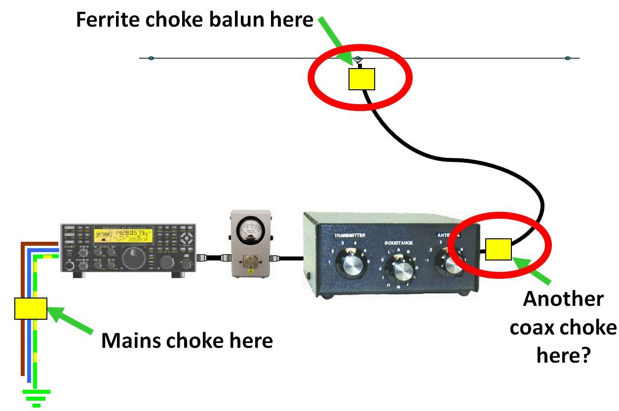
  • If you can block the common-mode current I3 by using a common-mode choke, you will force the antenna feedpoint currents to become much more equally balanced.

And that’s the private life of coax.

Clean Up Your Shack – 2019

The online follow-up to my talk for the 2019 RSGB Convention.

3 chokes

What’s new since 2015

DSC_0127

  • Constant changes in the prices of ferrite cores (but still the same Best Buy supplier)
  • Updated Whole-Shack Mains Filter

Capture.JPG

Downloads

  • Extended slide pack (PowerPoint) includes more slides showing how to build the updated Whole-Shack Mains Filter.
  • View ‘Clean Up Your Shack 2015’ (YouTube) for more detailed background.
  • Slides from my 2010 talk about chokes and baluns  to drill deeper into that subject.
  • All mains earth (green/yellow wire) connections are to the earth tag on the top end of the filter. 

THE PROBLEM SOLVER: Fair-Rite 0431177081 snap-on core

Not cheap, but well worth it. If RF noise threatens to take your hobby away, then surely it’s worth something to get it back?

  • Manufacturer’s data  Ignore the photograph – this biggest bead doesn’t look like that.
  • Current Best Buy supplier – and always near the top of the list –  is www.mouser.co.uk
    Again, ignore the photograph, trust the part number.
    Notice the big price break at quantity 10. This makes an ideal club purchase.
    UK prices are in GB£ but do not include VAT. However, that is all you have to pay. Three-day FedEx shipping from the USA is streamlined and free for orders over £50+VAT.

Parts list for the Whole-Shack Mains Filter

  • Packaged 15A or 16A mains filter, single phase, 250VAC rated.
    Within 2 days of publication, the Roxburgh RES5-F15 filter from Farnell was sold out! The specific type of mains filter is not critical, so instead let’s try the Schaffner FN2030-16-06 (also from Farnell, but many more in stock).
  • Large Fair-Rite core 0431177081: Mouser (see above) or Farnell
  • Qty 2, Fair-Rite oval core 2643167851: Mouser or Farnell
  • Plastic box CE-TEK GR17012 to fit the above parts: CPC  EN84544 
    NB: I said PLASTIC for a reason! A metal box opens up a world of unnecessary complications about earth continuity and de-tuning of the ferrite choke.
  • Qty 2, plastic cable glands, 5-10mm size: CPC CBBR7352
  • At least 3m of 3-core 2.5mm² mains flex, 90ºC rated: eBay, eg here
  • 13A socket strips to meet your requirements
  • 13A plugThe maximum total current supplied to all sockets is 13A, limited by this plug.

Steve Hunt, G3TXQ – In Memoriam

New Year’s Morning, 2019

G3TXQ was well known and respected throughout the technical world of Amateur Radio, through his website and countless postings to a wide range of groups and mailing lists. Always meticulous and deep-thinking, Steve was a fount of good information – and also a very nice guy.

Steve passed away peacefully on 30th December 2018 after a long battle with cancer, which he also recorded in that same meticulous manner.

G3TXQ is known particularly for his optimized versions of the Cobweb and Hexbeam antennas, and for his work on common-mode chokes. His website karinya.net is already archived at https://web.archive.org/web/20180428131952/http://karinya.net/
and if you haven’t already visited, I strongly recommend it. Take the tour, and you will meet the man he was.

Common Mode RF Chokes

G3TXQ-X

In addition to the material on his website about common-mode chokes, in 2015 Steve wrote a stand-alone article for RSGB’s online technical magazine RadCom Plus.  That article is in danger of falling into obscurity, taking with it some new information that has not been published anywhere else, so I am archiving it here in memory of Steve:

Common Mode Chokes: G3TXQ 2015

The article included a new version of Steve’s famous graphic to help in selecting broadband ferrite chokes to cover various HF amateur bands. The best chokes are the ones that cover the required band(s) with both the dark green shading and the black underline. Orange and red shading are to be avoided – the choke may do some good, but may also have problems. (For clarity, I have added a large ‘X‘ across the three chokes at the bottom. As Steve explains, those were included as particularly BAD examples, NOT to be copied.)

Writing this is not the way I had hoped to begin a New Year.
RIP, Steve.


VHF-UHF Baluns

This is the talk that I presented at the RSGB Convention in October 2018.

Update: RSGB have now released the video at https://thersgb.org/members/resources/?id=5762 (member login required; it will probably be several more months before the video is transferred to YouTube).

I always cringe to hear myself talking, but the sound track does add some context to the previously released slide pack ( still available here ).

Even without the voiceover, the important points are clear:

  • Today, “baluns” are about controlling interference, reducing noise
  • Choke baluns are best for doing this.

So we should aim to:

  • Minimize common-mode RF currents on the outside of the coax
    and along the boom.
  • Don’t upset the good feedpoint balance that VHF-UHF Yagis already have.

Comments and discussion, please!  This is new information for VHF-UHF, and certainly not the last words to be said about it. It’s still very much ‘work in progress’.
Leave a reply


Technical slide content © 2018 Ian White, GM3SEK
Slide template © 2018 RSGB
Images as attributed (except where that would be embarrassing).

Interdigital Filter Design

Here is a scanned pdf of my 1984 Radcom article called A Simple Way to Design Narrowband Interdigital Filters .

Doug McArthur VK3UM (SK) wrote a program to implement this design method. Since Doug’s legacy website has now closed, the program is now hosted here. Here  Click to download, then open the zip file and run the install program.

Many people have used this method – design your filter, build it well, and it will work.

A key requirement for good performance is an excellent electrical connection all the way around the base of each resonator element. Use a lathe to countersink the base and make a sharp, level edge all around (there is really no way to do this freehand). Drill and tap a deep hole into the base of each element, and assemble the filter using strong steel screws to pull each element tightly into the supporting bar (you’re actually hoping to make a cold weld).