The online follow-up to my talk for the 2019 RSGB Convention.
What’s new since 2015
- Choke Chart and RadCom Plus article by Steve Hunt G3TXQ (SK) – see separate blog entry below
- Revised Choke Cookbook by Jim Brown K9YC
- Large Fair-Rite #31 core
THE PROBLEM SOLVER! See ordering details below.
- Constant changes in the prices of ferrite cores (but still the same Best Buy supplier)
- Updated Whole-Shack Mains Filter
Downloads
- Extended slide pack (PowerPoint) includes more slides showing how to build the updated Whole-Shack Mains Filter.
- View ‘Clean Up Your Shack 2015’ (YouTube) for more detailed background.
- Slides from my 2010 talk about chokes and baluns to drill deeper into that subject.
- All mains earth (green/yellow wire) connections are to the earth tag on the top end of the filter.
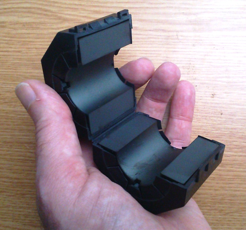
THE PROBLEM SOLVER: Fair-Rite 0431177081 snap-on core
Not cheap, but well worth it. If RF noise threatens to take your hobby away, then surely it’s worth something to get it back?
- Manufacturer’s data Ignore the photograph – this biggest bead doesn’t look like that.
- Current Best Buy supplier – and always near the top of the list – is www.mouser.co.uk
Again, ignore the photograph, trust the part number.
Notice the big price break at quantity 10. This makes an ideal club purchase.
UK prices are in GB£ but do not include VAT. However, that is all you have to pay. Three-day FedEx shipping from the USA is streamlined and free for orders over £50+VAT.
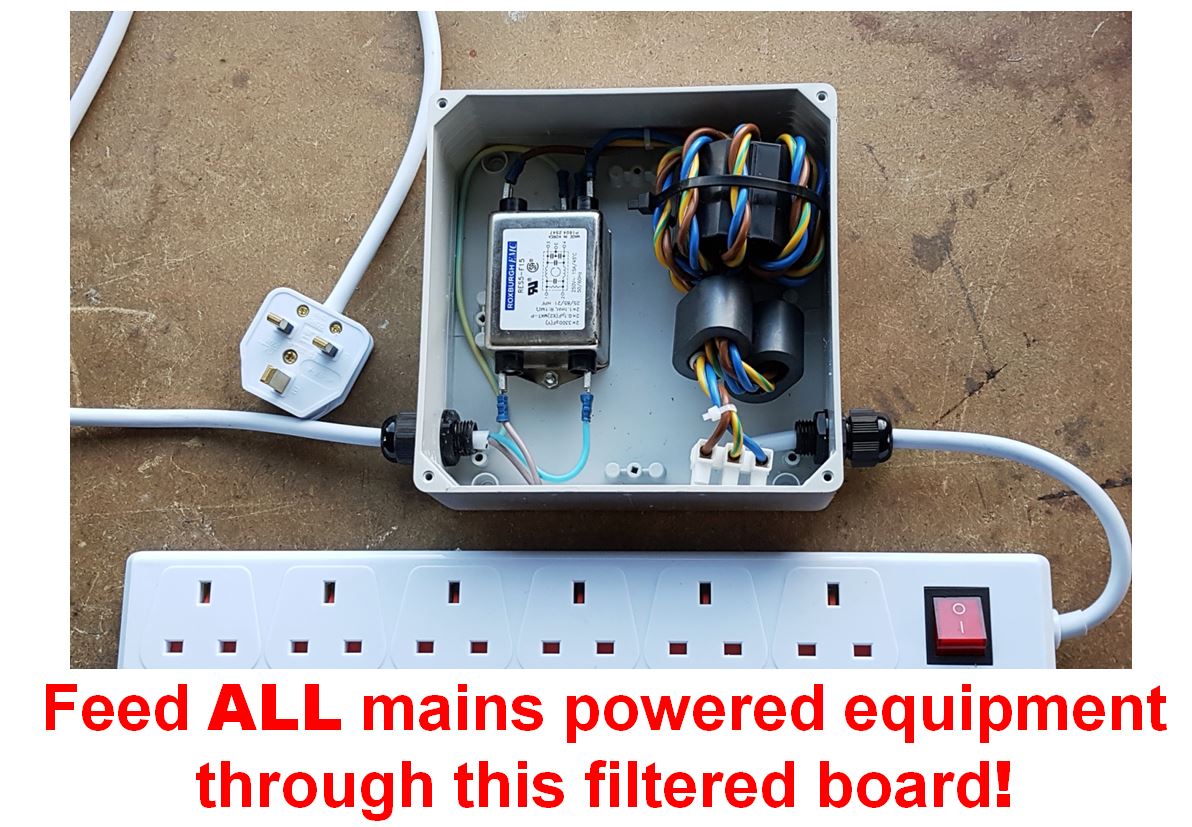
Parts list for the Whole-Shack Mains Filter
- Packaged 15A or 16A mains filter, single phase, 250VAC rated.
Within 2 days of publication, the Roxburgh RES5-F15 filter from Farnell was sold out! The specific type of mains filter is not critical, so instead let’s try the Schaffner FN2030-16-06 (also from Farnell, but many more in stock). - Large Fair-Rite core 0431177081: Mouser (see above) or Farnell
- Qty 2, Fair-Rite oval core 2643167851: Mouser or Farnell
- Plastic box CE-TEK GR17012 to fit the above parts: CPC EN84544
NB: I said PLASTIC for a reason! A metal box opens up a world of unnecessary complications about earth continuity and de-tuning of the ferrite choke. - Qty 2, plastic cable glands, 5-10mm size: CPC CBBR7352
- At least 3m of 3-core 2.5mm² mains flex, 90ºC rated: eBay, eg here
- 13A socket strips to meet your requirements
- 13A plug. The maximum total current supplied to all sockets is 13A, limited by this plug.

Good day
I attended the RSGB Convention and was pleased to be able to see your presentation on cleaning up the shack. I learnt a lot, and will be implementing many of your suggestions.
Recently I had decided to renew my coax feeders, and bought some Messi and Paolini Ultraflex 7 to do this with. From the data sheet, the minimum advised curvature in multiple bends is 68mm, giving coax loop diameters of 136mm, which might be acceptable at the antenna feed-point, but would be somewhat cumbersome at the point where the feeder leaves the radio. I intend to use 2 stacked FT240-31 toroids for the choke formers. I wondered therefore if RG58 which can be encouraged to a smaller diameter would be suitable for the choke construction, or perhaps you would suggest I should invest in some of the thin Teflon coax. In either case, the choke for use at the radio end would have to have connectors at each end in order to ‘splice’ it into the feed line. I have always tried to avoid unnecessary connectors in the feedline as I understood they would be sources of potential problems. Is the benefit likely to outweigh any issues that an additional 2 connectors in the feedline might provoke? (Maximum feedline length is 45m)
I usually work at 10W, with ocasional forays to 100w, and only rarely 400W. My location is semi-rural, and although I am not as plagued with nose as some of the recent correspondents to RadCom have indicated, anything to help seems to be a good idea. As I am making a change to my feeders, I would like to do the job just once, but properly.
Thank you for your talk, and the links to the other aspects of the topic.
73
Peter
M0RYB
LikeLike
Hello Peter
Glad that you enjoyed the talk, and I’m sorry it wasn’t possible to be there in person.
At the power levels you normally use, I would be inclined to wind the chokes with RG58. It will allow you to wind more compact chokes and will also handle 400W for occasional use. Don’t worry too much about connectors – good connectors, correctly fitted and well waterproofed, should never be a problem.
73 from Ian GM3SEK
LikeLike
Thank you very much, that is great.
73
Peter
M0RYB
LikeLike
Hi, I’m presently buying the components to make your mains filter, I understand why you’ve used a 31 and a pair 43’s however what about the lower frequencies? For complete coverage surely you should have a mix 75 / J in there somewhere as well? (I’m an avid LW / MW listener as well as the Ham bands). What do you think about half a dozen or so turns around a type 75 ring (or two of them, stacked) immediately after the twin 43’s? Thanks, Ali.
LikeLike
Hello Ali
Thanks for your comments. The filter that I showed was optimized for 1.8-30MHz, and I have not considered any lower frequencies. However, from the mention of #75 mix I guess that you have already read K9YC’s paper on ‘Chokes and Isolation Transformers For Receiving Antennas’ [1], where Jim shows some common-mode chokes for MF antenna feedlines that can easily be wound on small #75 toroids using twisted pairs from CAT5 cable.
[1] http://k9yc.com/RXChokesTransformers.pdf
The difficulty for a MF mains choke is the much larger wire diameter (three heavy wires twisted together) and the much smaller size of the available #75 cores – particularly the internal diameter through which the multiple turns of twisted wires must pass. On the positive side, extremely high choking impedances are probably not necessary for a mains choke because the prevailing system impedance is quite low. A possible candidate may be the 0475176451 snap-on core: if you reduce the size of the mains wire to 1.5mm^2 it may be possible to fit 4 or 5 turns through, which would give a useful choking impedance below 1MHz.
Obviously haven’t tried this myself but would be interested in any results.
73 from Ian GM3SEK
LikeLike
Hello Ian
Thanks for all the work you do make our hobby more rewarding. This may be a blindingly obvious question but where does the earth (green/yellow) wire go after it exits the large snap on? I can see that the live and neutral from the snap-on go to the commercial mains filter and also that all three wires from the mains go to the commercial filter. Many thanks, Bernard.
LikeLike
Hello Bernard,
The earth wire from the unfiltered mains input and the earth wire going to the RF chokes both connect to the “E” tag on the metal body of the mains filter.
LikeLike
That’s great, thanks Ian. I thought I’d seek clarity given that the mains is involved.
LikeLike
Having now built the filter exactly as described I can report a huge improvement in noise levels (S7/8 to S3 on 40m and 80m). These lower bands were off limits to me in the past as far as SSB went and now they’re not. Couldn’t be happier! Many thanks Ian for the work you have put in to offer RFI/EMC solutions to the Amateur Radio community.
LikeLike
Thanks, Bernard – that is always great to know!
LikeLike
Ian,
I wonder if it is acceptable to install the filters as part of a permanent installation? I am reluctant to ask my electrician to do this unless there is a precedent.. The reason for doing this is that more sockets could be protected by one filter.
73 Mike G4CDF
LikeLike
Mike,
I do not know the regulatory situation for a permanent installation, but it’s sure to be more restrictive than for a 13A extension.
If you only need more sockets than the 6-way board shown in the photographs, double-row boards are available up to 10 ways – always provided that the total load does not exceed 13A. However, there are also several other factors that limit the current capacity of this mains filter to 13A, including the 3-core flex, the number of turns that can be passed through the centre of the ferrite cores, and the current rating of the packaged mains filter.
Sorry that I can’t be more helpful.
73 from Ian GM3SEK
LikeLike
Ian, many thanks. I will follow your proven design as it is more flexible.
I have also seen your slides on VHF/UHF baluns. Apart form the baluns at the antennas do you recommend any filters on the rigs or supplies?
73 Mike G4CDF
LikeLike
Additional filters on commercial rigs should not normally be needed. ALL switchmode power supplies need filters on both input and output, but that topic is well covered elsewhere.
73 from Ian GM3SEK
LikeLike
Hi, i’ll be building the filter and have the parts on the way, thanks for all the research work here.
I’ll also be bonding my equipment as outlined in the clean-up-your-shack video, but i’m unsure if the bonding plate/braid should be connected to the filtered mains earth point or not??
Thanks
Dave (awaiting callsign)
LikeLike
Pingback: Clean Up The Shack – Part 1 – M6RUG
Yes, the mains earth connection on the shack side of the filter should be connected to the equipment bonding strip. That was mentioned in the 2015 talk, but I should have included it in the 2019 update as well.
LikeLike
Pingback: Clean up your shack – Part 2 – M6RUG
Hi Ian
Well thanks for all the info. I have just placed the order with Farrnell and CPC so hope to have the filter all built by weekend. I also ordered up the kit to build the CM Chokes as well. I dropped an email to your old blog posts if you can check thanks
John
LikeLike
Hi Ian
Quite simply, thank you!
Your filter design is working a treat on 20m and above with 3-4 S points of noise gone! 40/30 just 1 S point.
I did not manage to twist the wires together successfully and still get 7 turns so ended up with them flat.
Regards
Dave (M6RUG
LikeLike
Hi Ian,
Looking forward to building one of these. Any differences when dealing with 110VAC as opposed to 220?
73,
K5JBT
LikeLike
Hi John,
Two differences that I can think of, compared with 220/230V:
1. All AC supply currents will be multiplied by about 2. The practical limitation will be the current/temperature ratings of the twisted wires that you use for winding the chokes.
2. Also be careful about the ratings of the packaged mains filter (sorry, I have no experience about 110V AC).
73 from Ian GM3SEK
LikeLike
John,
Please let other North-American based Amateur know if your build worked just as well.
LikeLiked by 1 person
Dear Peter,
Regarding the Cost-effective Ferrite Chokes and Baluns (May 2010) article which is a similar topic. I was going to build these 3 frequency designs and noticd a comment that the 3 frequnecy design can be built as one unit (saving connectors) A silly question but is there a correct order that the 3 frequency designs should be built as one unit?
I have had great success with original 3 stage mains filter and built a couple of years ago the updated design with large core.. Noted you have now updated the build list to included a bigger box and changes due to availability of components.
Still use both mains filters so thanks for the designs.
Regards,
Bill.
LikeLike
Hello i want to ask some thimgs, the filter you use (Packaged 15A or 16A mains filter, single phase, 250VAC rated.) is it enough for the hole shack? PC ,rig, and other staff (only 16A)?
Aslo please could you explainto me both (earth s) goes to the same spot (earth spot) on the filter ? Thank you very much ! 73
LikeLike
For a typical “100W RF” station (no power amplifier), 13-16A should be more than enough current capability.
If you use a large power amp, that may increase the mains current beyond the capability of the board.of the board. (You have to measure the current yourself – I can’t tell you what it will be.) A power amp will require its own RF choke on all three wires of the mains connection.
The packaged mains filter only has connections for Line and Neutral. It does not filter the earth wire, so both earth wires connect to the same point on the metal case. (I would like to take a better photograph, but the filter is under lockdown at the radio club.)
LikeLike
Hi Pano
I have made the filter and used this type of connector:
https://uk.rs-online.com/web/p/crimp-piggyback-terminals/7187738/
to attached both earth wires to my commercial mains filter. If you live in the uk I have spares and would be happy to post you a couple. My email address is on QRZ.com … G8KVM.
Thanks
Bern
LikeLiked by 1 person
That is exactly what I already use, Bern – but thanks for the kind offer of course. Sorry that I can’t provide a better photograph at the moment.
73 from Ian GM3SEK
LikeLike
Pingback: The ongoing quest to reduce QRM – Mains Filter #2 | M7ALU Site
Added the updated filter to my shack – Thanks to Bern/G8KVM for the link. Its proving really valuable – many thanks for all your work – this filter is brilliant.
LikeLike
Thanks, Alan!
LikeLiked by 1 person
thank you – i was wondering with the filter, is there any tests/visualisations i can do with it by attaching it to an oscilloscope ? I’m all new (only licence in december) and eager to use the equipment and build up my knowledge of how to use it with an amature radio station. Scope is a rigol ds1202z-e
LikeLike
Hi Alan,
Since you only recently got your licence (and from “all new” I’m guessing you do not have any other electronics background) I strongly suggest you DO NOT try to make any measurements with your oscilloscope that involve direct connections with the mains! This can be dangerous – both to yourself and to the ‘scope.
Even experienced electronics technicians often do silly things when making measurements on the mains using a ‘scope. In particular, if anyone suggests disconnecting the earth wire at the mains plug, don’t listen to them!
Sorry that I can’t be more positive or helpful, but until you have a lot more experience, the risks are far greater than the benefits.
73 from Ian GM3SEK
LikeLike
Thanks again to you Ian. I was listening on 80 and 40m last night and until I built and installed the filter these bands were completely unusable. It’s really rewarding when something works so well.
Bern
LikeLiked by 1 person
Hi,
Thanks for your efforts with regards to the mains filter and for sharing it with us all !
Am I right in saying that a separate single core earth cable should be attached at the the mains earth connector block on the shack side of the filter and then ran to the grounding nut on the back of the transceiver ?
Sorry if I am asking a silly question here !
73
LikeLike
Hi Ross,
Yes, there should be a connection – but there are better ways to do this than a single wire. See the last 10 minutes of my 2015 presentation which talk about ground bonding using a broad metal strap cross the back of the operating bench.
73 from Ian GM3SEK
LikeLike
https://www.amazon.co.uk/gp/product/B0014GG7D8 – i use these and they work great. they come with a limited set of earth wires. I strip out the copper earth from kitchen-wire ampage to use for a cross-table connection. Everything bonds really well across tables without expensive copper piping being needed.
LikeLike
Hello Ian, I have just finished watching the presentation. The plan is to construct the mains filter and work on the bonding, chokes etc. I do moan about a noisy QTH, so need to get stuck in to this.
Towards the end of the presentation you talk about power supplies needing to not have the ground connected at the negative terminal, mine is, so opened it, crikey it’s not so accessible. However, this PSU is a switch mode unit, presumably it would be better to go linear?
LikeLike
Hello Ian,
Are you sure that the negative lead of the 12V output is connected to mains earth? (Meter reads zero-ohms between the negative lead and the case of the PSU, and between case and mains earth?)
A linear PSU is probably better anyway, but do confirm that you’re not buying another PSU with the same problem!
73 from Ian GM3SEK
LikeLiked by 1 person
Hi Ian,
Thanks for replying. Zero ohms between the negative connection pillar and chassis or with a kettle lead plugged in the earth pin, chassis and earth pin obviously zero ohms too. That is with everything unplugged from the PSU. So, certainly seems to be connected inside, I’d need to dismantle this quite a bit to get at the connection. It’s several years old and was bought used, probably time to replace it soon anyway.
73,
Ian MM0GYX
LikeLike
I need help. I have this noise in my Icom 7300. I using the PS Astron RS-35A with one filter inside that I install yesterday but the noise persist. I have also the ugly choke with 10 ft in 4” pvc. I can’t to kill this noise in 15 Mhz to 30 Mhz. I using the Sirio 827 10-11M vertical antenna and the coaxial RG8x TRAM TRAMFLEX 112 ft…. https://www.youtube.com/watch?v=o3SU-1aN-Vw&t=2s
LikeLike
Michel, it is very difficult to help you from this long distance.
The best way forward that I can recommend is to buy *2 or more* of the large Fair-Rite #31 snap-on beads and try the effect of making chokes of 3-5 turns at various places on your system. The first place to start is at the feed-point of your vertical antenna. If a choke makes some improvement, then leave it there and continue with another bead in other places.
Sorry, I know that those beads are very expensive. They are expensive everywhere outside of the USA but there is no alternative.
73 from Ian GM3SEK
LikeLike
I have built Ian’s mains filter as described and am happy to report a reduction in noise which makes 17m now usable. I still have noise coming in on the antenna and have ordered even more ferrites from Qubits (I dont know what the guy must think of me as recently have been one of his best customers.) I found the filter very straightforward to build with the components identified by Ian
LikeLike
Thanks for posting here, Tom. There is no substitute for real-life user feedback!
LikeLike
Hi Ian
I am in progress of building your mains filter. I also want to fit chokes on all the incoming antenna cables. In the interest of neatness I would prefer to put all four of them in one plastic box. Two of them are tx antennas and the other two are a Beverage and a remote rx mag loop. If all ferrites were in one box would there be an unacceptable level of cross coupling between the high power tx ones and the rx ones which go straight to the separate rx input on the radio?
PS do you remember the Romford club in the 60s?
73 RIchard G3OQT
LikeLike
Hi Richard – great to hear from you, and I hope you’re well in these strange times. I do indeed remember the Romford club (but somehow the mornings-after are a lot more hazy).
There should not be much coupling between different chokes in the same enclosure. Good ferrite chokes will keep the common-mode currents very low, and any residual external fields will be confined very close to the separate cores. But having said that, why risk it? If you use one box for the TX chokes and a separate one for the RX chokes, that will reduce the coupling even further and could open up even more options to try, like in-band listen-through (which immediately brings back LUI-Dick’s tales of full duplex CW in the RAF).
73 from Ian GM3SEK
LikeLike
Hello Ian and Richard,
Ian, I have looked at your projects over the years and have found them extremely interesting.
I have done a lot of ferrite work myself especially with HF and VHF couplers and combiners.
Like you and Richard, I have many fine memories of the RAFA club!
73s,
Howard, G3PGN.
LikeLike
Cheers Howard – good to hear from you!
LikeLike
Hi Ian
Built your Mains Choke and fitted a 13Amp switched socket into the box and really pleased with the result both aesthetically and practically. 80m looks a lot better now.
Thanks very much
Dave. G3SBP
LikeLike
Thanks, Dave, that’s really good to know.
73 from Ian GM3SEK
LikeLike
Hi Ian,
One more happy chap here. I have now less noise on 40 & 80. Thanks for sharing your knowledge !!!
73 Gopan
M0XUU / VU3HPF
LikeLike
Hi Ian,
thanks for the information here, very interesting. I’m in the process of building the mains filter and have, what is probably a bit of a dumb question, but as this is mains electricity we’re talking about i thought i’d check.
I’ve got the Schaffner filter and just need to clarify the connections to it. The earth has 1 tag, and is unfiltered, so 2 connections are made there. But, which side do i connect to the plug end? I assume the ‘Load’ connects directly to where the 13A plug is connected in your photo and the ‘Line’ then feeds directly to the Fair-rite cores? Just thought i’d check
cheers
Dave
M0IKT
LikeLike
I’m interested in the answer too, I set mine up the other way around. Line to plug, radio equipment etc to load.
LikeLike
Apologies, Ian – please see my answer to Dave.
73 from Ian GM3SEK
LikeLike
Sorry Dave, I thought I had replied to this one, so thanks to Ian MM0GYX (who has the same question) for reminding me I hadn’t.
I don’t think the way-around of the packaged mains filter is a major factor. Choosing to place the end with the earth tag closest to the RF choke was simply for convenience. It’s much easier to wind the RF chokes if all three wires are the same length.
However, I would be very interested to learn of any cases where turning the filter around does make a difference. (You will recall that I haven’t laid eyes on the prototype since February, because the building that houses our radio club remains under lockdown.)
73 from Ian GM3SEK
LikeLike
Hello Ian,
According to Schaffner’s datasheet for the single-stage filter FN 2030 it does seem to matter which way around the mains is terminated. The circuit diagram, on the datasheet, shows the load and line terminals. That goes for the Roxburgh filter as well.
The datasheet for the FN2030 can be downloaded here…
Click to access 2340758.pdf
I have noticed that there seems to be some confusion as to which is load and which is line. Load is the equipment side of the filter (output) and line the mains from the socket (input).
I ordered the two-stage filter FN 2090 as I needed to spend £33+ to qualify for free p&p from Mouser. I’ll let you know how it goes when I’ve built it.
73s John M1JJK.
LikeLike
I came across your blog yesterday, and was immediately spurred into action by your ” how to clean up your Shack” piece. Like you, I live in a rural area, and noise isn’t really a problem. For years I’ve always used Choke BalUns on antenna feed points, AND at the rig end of feeders. I have also exhorted anyone who’d listen, to do the same. Your mains filter grabbed me instantly, (Why didn’t I do it years ago??) and I immediately built it from my junk box. I didn’t have the clamp on #31 ferrites, but I had everything else. I have plenty FT 240 31s, so I stacked two of those instead. The result was immediate, and pretty dramatic. Previously whenever I’d point the Quad, or my 40m phased verticals, towards the house, the noise would increase quite a bit. Now, the noise floor remains constant thru’ the full 360 degrees rotation of the Quad, and the phased verticals are nice and quiet LP to VK/ZL.
I have a length of steel box conduit, about 75mm square running along the back of my operating desk. This acts as a buss bar, and mains and 12V distribution system. To that I have connected 150mm wide copper flashing,(low inductance) which runs to the outdoor radio ground system. I built the mains chokes inside the steel conduit, as there is plenty room, and good mains grounding. I’m extremely pleased with the result.
Thanks for doing all the hard bits for us, and for posting the info on your Blog. I’ve enjoyed your interesting, and very useful contributions over many years.
Vy 73 to u es urs
John EI7BA
LikeLike
Thank you, John!
LikeLike
I’ve ordered up a couple of those ferrites to build another filter, as i intend to separate the computer gear from the radio stuff, and put ’em on a different socket. I’m also curious to see if there’s any obvious difference between the clamp on, and my toroids. A posh job this time, as I’ve got all the bits as specified in your article. {;o)
Vy 73
John EI7BA
LikeLike
I have built the mains filter as per your article and it works great for me. Thanks for all the work you put into this project
Best 73
Liam EI2BWB
LikeLike
Hi Liam,
Thanks – delighted to hear it!
73 from Ian GM3SEK
LikeLike
Hello Ian,
Now I built the mains filter. I checked all bands 160 – 10m with my transceiver CW 500Hz filter.
I could not see any difference before and after connection of the mains filter. On for example 80m I have 3.5 S-units. Would I have noticed a bigger difference if the noise level would have been higher e.g. S9?
73 de Len SM5ENX
LikeLike
Hi Len (and apologies for the delay).
Sadly, the one thing I cannot predict is if any individual user will actually have a problem with interference on the mains. If you do not have that problem, then the filter cannot help you
The best thing you can do is to pass it along to someone who does have that problem.
73 from Ian GM3SEK
LikeLike
hi ian just say ive just mais the filter and had great success on 160 and 80 …160m down 3s units to an s3/4..80m down 2/3 to an s3/4 … not too uch chage on 40 or 20….. mamy thanks for your help and all your publications
steve M0EBJ .norwich
LikeLike
Hi Steve,
Thanks – delighted to hear it!
73 from Ian GM3SEK
LikeLike
Pingback: Fabrication d’un filtre secteur – F5SVP
Hello Ian,
If the coax shield is earthed before it comes into the shack either via a lightening arrester or by passing the coax through a metal bulkhead using bulkhead connectors would this remove the common mode currents?
LikeLike
Hello Colin,
Good question – thanks for posting. The quick answer is that earthing the coax outer shield at the house or shack entrance can only remove some fraction of the CM current.
Whenever a current has more than one choice where to flow, it will divide among the possible pathways in the ratio of their respective impedances. In order for a dedicated ‘RF earth’ to divert most of the CM current away from the shack, it would need to have a much lower impedance than the mains earth itself – we’re probably talking about a small fraction of an ohm, which is practically impossible.
The other problem is that if the electrical length of the feedline (the outside surface, not the inside) is a half-wavelength, then even quite a poor earth at ground level will create a low CM impedance up at the feedpoint, which positively invites more CM current to flow. This is a particular problem with coax-fed multiband antennas, where there’s sure to be a resonant feedline on some band or another.
Yet another problem is that the Wiring Regs require all additional earth electrodes to be bonded back to the consumer unit – which is often conveniently ignored. But worse still, if you do that you’ll be connecting your so-called “clean” RF earth directly to the dirty mains! (The only way around that is to install ferrite chokes on the bonding conductor as well.)
Unfortunately RSGB training materials and even the exam syllabus promote a dedicated RF earth as something that will always be a benefit to EMC. ARRL materials are much more accurate and realistic about this.
73 from Ian GM3SEK
LikeLike
Hi Ian,
Getting ready to build one and wondered if using a metal box was acceptable?
Thanks & 73,
JIm WE4S
LikeLike
Hi Jim,
A metal box is not needed, and it will only add unnecessary complications: you must connect it to ground, and there may be some de-tuning of the chokes due to capacitance.
The ground connection would be problematical (input or output side?), and it would definitely affect the performance of the filter. I have no experience of this, so I’m afraid you would be on your own.
73 from Ian GM3SEK
LikeLike
Thanks Ian,
I knew there would be more issues that I hadn’t thought of.
Happy Holidays.
73 Jim WE4S
LikeLike
Many thanks for the information Ian. I’ve just ordered the components to build the mains filter.
I do have a question many people struggle to answer and would like to hear your opinion.
My shack in on the first floor bedroom with no dedicated earth. My antenna is end fed with no counterpoise and works great (apart from the noise which im address). My concern is running a length of earthing cable from the 1st floor bedroom to a dedicated earthing rod to ground will create havoc with RF, i.e the length of earth wire creating another antenna.
Do I load up with ferrite and make do? or is there something I haven’t been told?
Keep safe 73’s de Paul 2E0YHQ
LikeLike
Hi Paul,
As you suspected, there is something that you haven’t been told. The UK exam syllabus promotes the myth that you will always need a dedicated “RF Earth”. What it doesn’t tell you is that you often DO NOT, and that attempting to provide one (especially to an upstairs shack) can often make things worse, increasing the noise pickup on receive and also increasing the risks of causing interference on transmit.
Obviously you always need a mains safety earth, and that does not change when you install the filter. However, your end-fed half-wave (EFHW) antenna does NOT demand a good, short connection to earth – it can function perfectly well with only a short counterpoise that carries a relatively small RF current. The reason why EFHW antennas often don’t seem to need a separate counterpoise is that they’re rather good at “finding” some other short length(s) of wire in your installation to serve the same purpose. This is often the outside of your coax feedline, but you need to be aware that the RF current will then come into the shack… and potentially beyond.
The ferrite chokes in the mains filter will block these wandering RF currents from travelling any further into the mains. Another possibility to try would be RF choke(s) where the coax enters the shack (similar to the mains chokes, but wound with coax instead). As well as checking the RF noise level, you can also monitor the effects of your changes by running a set of VSWR curves “before and after”.
73 from Ian GM3SEK
LikeLike
Quote”What it doesn’t tell you is that you often DO NOT, and that attempting to provide one (especially to an upstairs shack) can often make things worse, increasing the noise pickup on receive and also increasing the risks of causing interference on transmit.”
Exactly my situation – upstairs shack, i had a ground rod installed and properly bonded to the supply ground as required by our supply setup – it made things a lot worse so i disconnected it and not looked back.
I currently run a 10-40m doublet with ladderline right to the bench/AMU and it works perfectly. I built your mains filter a long time back and that seems good too.
LikeLike
I have a similar filter to the Schaffner in stock 20a rated, cable glands will be delivered tomorrow. In the meantime I have cut the plug off a 4 way distribution lead and fitted a pair of FT240-43 toroids, I know this differs from your design but it looks very promising so far, HF antenna is a ground mounted “fan vertical” with ground stakes and radials. I do have common mode chokes on the feeder at the shack.
LikeLike
Hi Ian, I have not yet built the full device but I do have a 20a filter ready for the project, yesterday I thought I would try the common mode choking alone and it certainly seems to help. I was a bit surprised as the antenna feeder has a generous amount of common mode choking too.
I also have common mode chokes on other things that want to radiate, such as the feeder to the satellite dish and the phone line. Various measures have contributed and it has done a lot to restore the hobby for me. 73s
LikeLike
Hi I have a standalone shack about 20m from the house with it’s own fuse box, I was wondering if it would be possible to connect the filter to the wiring coming from the fuse box that feeds my shack sockets instead of just an extension?
LikeLike
Hi Ian,
The answer depends on how you connect the mains feed to the shack. At a distance of 20m from the house, it is probably best to install a completely separate earth connection for the shack. This will require a short connection to a good, deep earth spike, but NO connection to the house earth. In that case, you may not need the ferrite chokes at all.
However, I would still recommend the use of a packaged mains filter. Connect the L and N from the house feed to the end of the filter that has only two insulated tags – and DO NOT connect the house earth at all. At the opposite end of the filter there are three tags which you should connect to the L, N and E of your distribution board. That means your shack earth will be connected to the tag on the metal case of the packaged mains filter.
Also DO NOT run any other cables (RF coax, Ethernet, phone) between the shack and the house. Use WiFi and other wireless-based alternatives instead.
For further safety information, see these two publications from RSGB:
http://rsgb.org/main/files/2019/12/EMC07-v4-Earthing-and-the-Radio-Amateur-Basic.pdf
http://rsgb.org/main/files/2019/12/UK-Earthing-Systems-And-RF-Earthing_Rev1.4.pdf
73 from Ian GM3SEK
LikeLike
I’ve been assembling this unit in a metal box and thus the casing is earthed as well. I have also mounted a double mains socket into the case which has earthing for the mounting screws connected to the earth pin of the socket (normal configuration). I’ve just realised therefore that the earth is common to the input and out put of the chokes. thus for the purposes of the earth wire the inductance is shorted. Will this make a difference?
LikeLike
It certainly will – I specified a PLASTIC box for good reason! A metal box opens up a world of unnecessary complications about avoiding unwanted earth continuity, and it is also likely to de-tune the ferrite choke.
73 from Ian GM3SEK
LikeLike
Thanks, useful to know. Back to a plastic box
LikeLike
Hi Ian,
The Fair-Rite oval core 2643167851 seems to either be out of stock or with a minimum order of 10 to 25 pieces. Would an FT240-43 toroid be an acceptable substitute, or is the binocular type core made from the two oval cores essential?
Is there not really an acceptable substitute for the large Fair-Rite core 0431177081 (someone suggested stacking 2 FT240-31 cores)?
Thanks,
Chris
LikeLike
Good day,
I’m planning to make a same implementation like you did excellently in this article . I’m not certain however if the 3 wires are need to be twisted , as without twisting I would able to loop through the wires more times in the ferrite core .
LikeLike
Good day,
I’m planning to make a same implementation like you did excellently in this article . I’m not certain however if the 3 wires are need to be twisted , as without twisting I would able to loop through the wires more times in the ferrite core .
LikeLike
Hi,
I’ve just purchased the component’s to build the mains filter. I have a question on you RSGB presentation which is excellent, You talk about linking to radio and psu etc with pc board and braid do you have any more info/photos and where to buy it from. sorry for a basic question i am new to amateur radio. many thanks
Lee
LikeLike
I had some issues with a high noise floor and also my VDSL broadband dropping upon transmitting (even at 5 watts on FT8).
I had some spare “problem solver” Fair-Rite beads so I set about building. I also built a notch filter for my phone line to notch the 40m band. (see here: https://3fs.net.au/amateur-radio/40m-vdsl-filter-for-your-nbn/)
The combination of both of these appears to have cured my issues.
I have not earthed any of my equipment as the electrical supply to my house is a TN-S system which I know has some implications with creating earth loops etc. This is something I am going to investigate next.
Thanks,
Matt
M6MVW
LikeLike
Hi Ian,
Moved QTH recently, and had to rebuild the shack. I decided to incorporate a mains filter and Chokes in the antenna feed, at both ends. ( as per your presentations )
This has made 80M usable, where before I had S9 noise. Improvements as well on the other bands, but the biggest was on 80.
Thanks for making this information available, with a practical path to implement it.
The Ferrites are not cheap, but the improvements are priceless.
Peter vk3apw
LikeLike
Hi Ian!, thank you very much by the nice article and the careful organization of the information. Yesterday I have finished my Mains Filter, and I got a huge reduction of noise, taking into account that I live in an urban envioroment. Very good sudy and practical conception, and first of all your generosity, sharing your experiences!. 73
LikeLike