How to operate a 24V relay with no 24V DC supply.
It only needs this simple circuit.
BOARDS NOW AVAILABLE – order here
Most amateur equipment operates from 12-13.8V DC; but many of the best RF coaxial relays are military surplus and designed to operate from 24-28V DC. Obviously you can generate 24-28V using a switch-mode power supply operating from 12V, and circuit boards are very cheap on eBay. But that isn’t the only way to do it… and not always the best way, either.
“Relay Speed-up” Circuit
This little circuit was originally published in my Radcom ‘In Practice’ column for April 2002 as a way of speeding up the slow open-frame antenna changeover relays that are used in many older power amplifiers. It works by providing a switching pulse at twice the normal voltage, which will roughly halve the switching time. For more details, download the Radcom article.
The idea appears to have originated with K1KP and K6XX. To make it compatible with the switching outputs of most modern transceivers, I added the low voltage / low current switching interface (TR1) so the final circuit looked like this:
Corrections: TR1 should be ZVN3306A (or 2N7002) and TR2 should be ZVN3306A (or similar)
Fig.1: Relay speed-up using a pulsed low-side switch.
Notice that the relay(s) are connected to the positive supply rail, and the switching circuit TR2-TR3 is connected at the ‘low side’ between the relays and ground. For that reason, this type of circuit is often called a “low-side switch”.
Alternative Use: Operate 24V Relays from 12-13.8V
This same circuit also has another use: it will allow the large majority of 24V relays to function directly from a 12-13.8V DC supply, with no 24V supply at all! This is because most so-called “24V” relays only need the full voltage while actually switching over. Once the relay has pulled in, most “24V” relays will hold in quite satisfactorily on 12V or even less. So there’s actually no need for a continuous 24V supply – all you really need is that first short pulse.
If a low-side switch is what you need, simply connect Fig,1 to a 12-13.8V DC supply rail and most 24V DC relays will function almost as normal. However, we can simplify it a little more…
Now Even Simpler
Fig.2 is even simpler than Fig.1 was. We have now converted the whole circuit into a ‘high side switch’ which no longer needs a separate control interface. The active switch is connected between the supply rail and the relay; and the ‘low’ side of the relay is connected directly to the ground return. We can now control the relay directly from the gate of Q2, so Fig.2 is simplified to just the two transistors and a handful of other components.
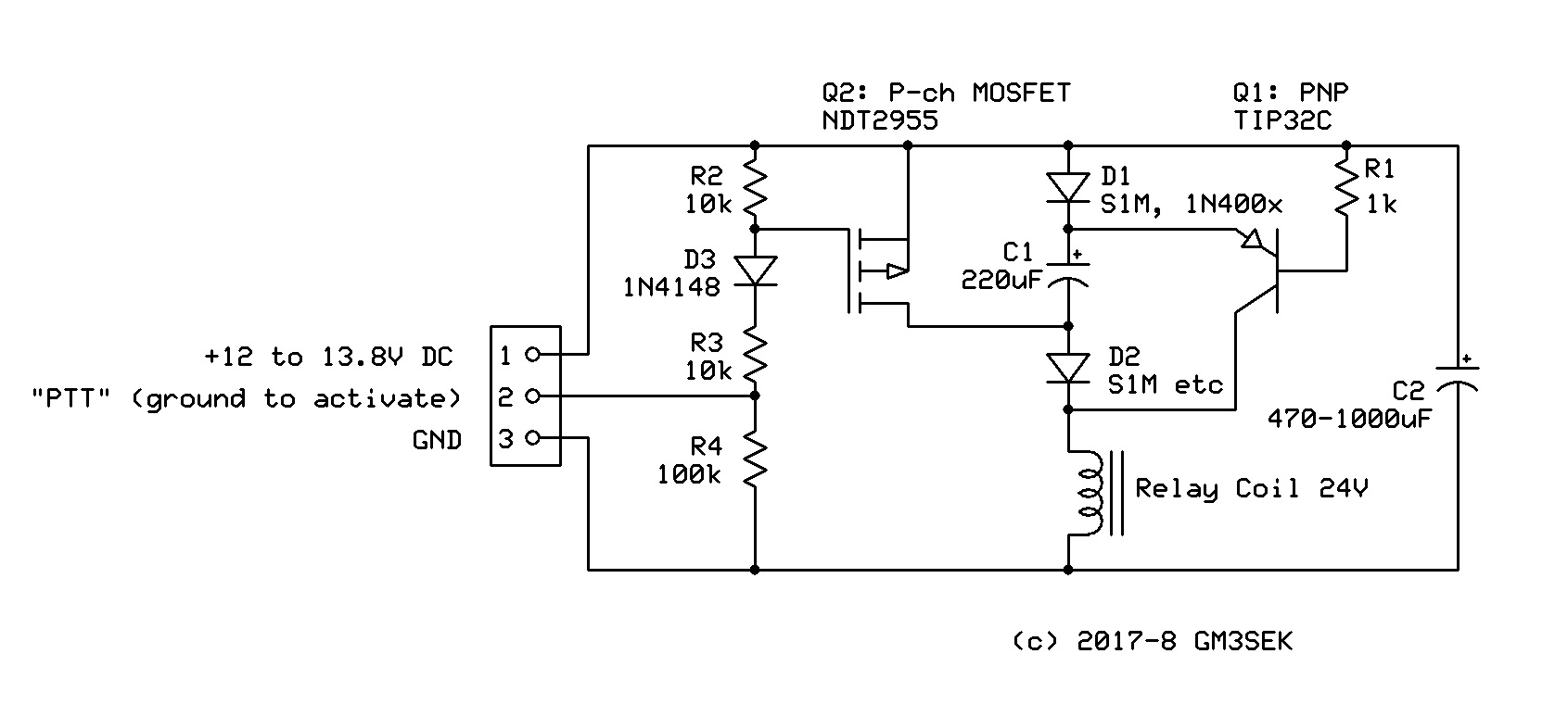
Fig.2: High-side pulsed switch.
Parts List for Fig.2
C1: 220uF 35V, 10mm dia, lead spacing 5mm (eg Farnell 9451293 )
C2: 1000uF 35V, 13mm dia, lead spacing 5mm (eg Farnell 9451323 )
D1, D2: S1M (SMD version of 1N4007, eg Farnell 2675069 )
D3: 1N4148 SMD (eg Farnell 2677464 )
Q1: TIP32C PNP bipolar, TO220 (eg Farnell 9804161 )
Q2: NDT2955 P-channel MOSFET, SMD (eg Farnell 9846271 )
R1: 1K0 0805 SMD (various sources)
R2, R3: 10K 0805 SMD (various sources)
R4: 100K 0805 SMD (various sources)
CIrcuit Notes for Fig.2
About C1 and C2: C1 is the capacitor that adds an extra 12V pulse in series with the permanent 12-13.8V supply. The value of C1 usually isn’t at all critical, and in most cases 220uF will give a switching time almost identical to what you’d see with a conventional 24V supply. You can experiment with different values for C1 while using an oscilloscope to monitor the pulse shape and voltage.
C2 is a reservoir capacitor connected across the 12-13.8V supply rail, to help meet the pulsed current demand. If the relay is mounted remotely (eg at the masthead) then the whole circuit needs to be located close to the relay itself, but the presence of C2 at the load end of the supply cable makes it unnecessary to use heavy wiring.
C1 and C2 see no higher voltage than the 12-13.8V supply rail, so a typical voltage rating would be 16V. (Higher voltage ratings are perfectly OK, of course; but not actually needed.)
Do not connect a ‘protection’ diode across the relay coil – it isn’t needed. The switch-off surge is absorbed by recharging C1 and C2.
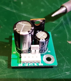
The whole circuit can be built on a scrap of Matrix Padboard (search eBay.co.uk) or Veroboard. To fill some free space on a PC panel that was mainly for another project, I made a very compact semi-SMD version as shown in the Lead Photo and Fig. 3.
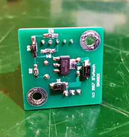
Fig.3: Compact version of the pulsed high-side switch.
Page © 2017-2021 IFWtech (Ian White, GM3SEK)
Fig.1 and related links © RSGB

Please make some PCBs available, this is very useful. I’ll buy 10!
73
Conrad PA5Y
LikeLiked by 1 person
I’ll certainly think about that. Anyone else interested?
LikeLike
Yes please! I’ll have four, please. Russ, G4SAQ
LikeLike
Larry VK6NOL used the board to drive a 28VDC waveguide switch with a very low coil resistance of 17 ohms, and requiring a much larger pulse than an ordinary relay. C1 and C2 needed to be increased to 10,000uF each, and R2 reduced to 500 ohms.
LikeLike
Ahh must have just missed the last batch. It was the note re Larry that appeared in my email box to notify me. Away bnow for 4 weeks but I’ll check when I get back. Russ, G4SAQ
LikeLike
New batch of boards just in – PayPal buttons will reappear shortly.
How many do you need, Russ (1-4)? Happy to save them for you.
LikeLike
Thanks Ian. I’d like 4 please. Not off until the w/e so may be able to purchase this week. Is 1 postage payment good for 4? Russ
LikeLike
The BUY NOW button is back!
Sorry about the intermittent supply, but in order to maintain a low price I have to order in small quantities with slow shipping. This makes it difficult to maintain stocks, but the alternative would be a 2-3x jump in price.
LikeLike
Hi Ian
I would like 2 of your boards please.
LikeLike
Hi Alan
Sure – boards are in stock. Please click “Odd Boards For Sale” at the top of the blog page, and follow the PayPal link.
LikeLike
Hi Ian,
Received your board 2day, really cute little thing.
I just wonder since its not easy to get those part here where I live,
is it possible for you to supply the needed parts?
I will then ad another 2 pcs, the it will be parts for 3 boards.
I that by any means possible ??
Kind regards
Hugo LA5YJ
LikeLike
I am very sorry, Hugo, but I do not supply parts. I have plenty of boards, but I do not keep parts (not even for myself).
Have you tried https://no.farnell.com/ ? Farnell UK will accept private orders by credit card.
LikeLike
Hi. Interesting design. ANy tips on how i could modify it to switch 12V relays on a 5V/6V supply? How much of the circuitry would i have to change?
This is to try to find cheaper relays for the x-phase local noise reducer circuit such as shown on VK5TM’s site.
Thanks.
James
LikeLike
Thanks for the comment, James, and apologies for this delayed reply,
Performance depends very much on the individual type of relay, but successful operation at lower voltages is less likely. This is because the voltage drops across the semiconductors junctions in D1, D2 and Q1 all remain essentially the same, regardless of the supply voltage. With a 12V supply these voltage drops are not very important, but at lower supply voltages they become a much bigger fraction of the voltages supplied to the relay..
LikeLike
Hello Ian,
Not sure if you still supply the PC board for 24V relay and the DG8 bias Tee?
If yes I would order 2 of each (if you can ship to France).
73 de Jean-Louis F5DYD
LikeLike
The boards are still available, and I am always happy to ship to other countries!
(Jean-Louis, I have also sent you a direct message.)
73 from Ian GM3SEK.
LikeLike